What is MBD Analysis?
Multi-Body Dynamics (MBD) is the simulation discipline that analyses how assembled mechanical systems move — tracking the position, velocity and acceleration of each part and computing the forces transmitted through joints and contacts.
It bridges the gap between CAD geometry and dynamic reality — answering how your mechanism behaves under real motion, not just under static loads.
MBD is often used to extract joint reaction forces and input them into subsequent FEA — giving you the most accurate structural loads for design validation.
- Position and motion trajectories
- Velocity and acceleration plots
- Joint reaction forces and moments
- Constraint force extraction
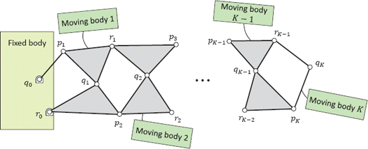
- Kinematic chain analysis
- Flexible body coupling (MBD+FEA)
 MBD — Mechanism Motion Simulation
How It's Done
Joint Definition
- Revolute, translational, cylindrical joints
- Fixed, spherical and slot joints
- Contact pairs (rigid-on-rigid)
- Degree of freedom count verification
Motion Inputs & Forces
- Prescribed angular / linear motion input
- Applied torques and forces vs time
- Gravity loading
- Spring and damper elements
Solve & Post-Process
- Rigid body equations of motion
- Velocity and acceleration at each body
- Joint force and moment extraction
- Motion animation generation
FEA Coupling (Optional)
- Export joint forces to structural FEA
- Flexible body MBD for stress estimation
- Fatigue life from force history cycles
Simulation Results
Mechanism Motion — Assembly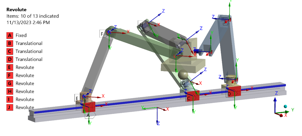 Joint Reaction Force History
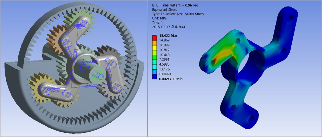 Velocity Profile — Rotating ComponentAcceleration — Linkage Output
What You Receive
| Deliverable | Description | Format |
|---|---|---|
| Motion Animation | Animated assembly motion through full operating cycle | MP4 / GIF |
| Force Time Histories | Joint reaction forces and moments as functions of time | Excel / PDF |
| Kinematic Plots | Velocity and acceleration at key bodies and output points | Excel / PDF |
| Engineering Report | Methodology, joint definitions, results interpretation and design guidance |
Industries & Applications
Mechanisms & Linkages
Four-bar linkages, crank-slider mechanisms and complex kinematic chains — motion path and force analysis.
Rotating Systems
Gear trains, belt drives and shaft assemblies — torque transmission and bearing load extraction.
Machine Assemblies
Industrial machinery with multiple moving components — joint sizing and lubrication load basis.
Robotic / Automation
Articulated arm kinematics, actuator force requirements and collision trajectory evaluation.
Understand Your Mechanism's Dynamic Behaviour
Share your CAD assembly — we set up the joint definitions and motion inputs and deliver results within 7–12 working days.